CategoriesCalendar
ArchivesQuicksearchSyndicationStatisticsLast entry: 2012-09-11 21:41
38 entries written
446 comments have been made
26 visitor(s) this month
6 visitor(s) today
0 visitor(s) online
Powered by
|
Sunday, January 29. 2012Instrument Tuner - Zero Crossing analysisHaving captured audio over a microphone, and converted to a voltage suitable for the Arduino ADC, the next challenge is capturing the analogue data and converting it into an estimation of the frequency of the current note being heard. That's a fairly tricky problem, as it turns out. Firstly, the default Arduino analogRead() function is way too slow. At 100 microseconds per read, that's a maximum sample rate of 10kHz - and even that is only possible when tight-looping doing reads, and nothing else. According to Nyquist's theorem, at a bare minimum I need to be able to sample at at least twice the highest note's fundamental frequency, which is probably going to be about 1kHz, so double up to 2kHz. I'd ideally like to sample at least 5-6 times the highest fundamental, and calculating the incoming frequency requires some maths too. So, I decided to look into alternative approaches. A naive approach to frequency counting is to count zero-crossings in a given direction - i.e. observe the waveform, and everytime it goes from negative to positive, increment a counter. Counting the number of crossings in a given time directly gives you the frequency. It turns out that both the ATTiny85 and the ATmega328 (Arduino) chips both contain an analogue comparator, hooked up in such a way that zero crossing counting can be done extremely efficiently. The principle is to compare the input voltage against a reference voltage, and tell the comparator to issue an interrupt when the comparison of the two goes from positive (input > reference) to negative (input < reference) - that's our zero crossing. By counting every such interrupt, and maintaining an accurate reference clock, we can determine the number of zero crossings in a second - which directly gives us the frequency in Hertz. Remember that I had applied a 2.5V DC offset to my original AC signal. By setting up a potentiometer between 5V and 0V, I was able to generate a variable reference voltage, which I set to close to 2.5V. Here's a trace of a simple pure sine wave as the input voltage:  Simple sine wave input (in blue) and reference voltage (yellow). Why did I say "close to 2.5V"? Well, the problem is that there's quite a lot of noise in the input signal. If I set the reference voltage at exactly the zero point of the AC signal, then I'd wind up counting an awful lot more zero crossings than I want to: 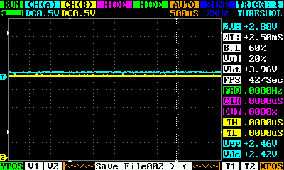 No active input to the microphone still gives a noisy signal, so the reference voltage is set slightly off from zero. So far so good. Setting up the analog comparator to support this is trivial:
I also had to do a bit of work to set up an accurate time reference (I chose a 1ms rate) to collect the zero-crossing counts at regular intervals, and convert them into crossings-per-second. Here's a handy utility function to do just that:
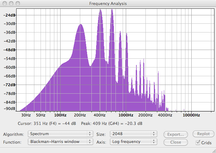
Testing this against some reference sine waves gave very promising results - I was generally within a couple of Hertz of the expected value, which is great. My signal generator doesn't go above 20kHz for sine waves, so I switched over to square waves and tried to see what the frequency limit of this approach is. To my surprise, I was still getting accurate readings up to 200kHz. At 500kHz input signal, things finally broke down and I got a reading of about 250kHz - still pretty good! But I said that this is a naive approach. It turns out that real-world waveforms from actual musical instruments don't play well with zero-crossing analysis. To see why, let's look at a sample waveform from a ukelele: 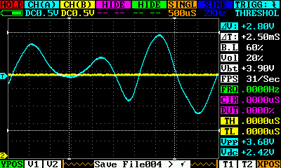 Portion of the waveform from a ukulele recording. That's pretty far from a pure sine wave, and the reason is because of all the harmonics. Running a Fourier transform on the signal shows the spectrum distribution:
It looks like the fundamental frequency here is around 200Hz, but there are stronger (+6dB) harmonics at 400Hz, 600Hz, and onwards. Those will seriously distort the zero-crossing counting - and indeed, I don't get any steady counts when listening to the ukulele. Damn. The standard approach to dealing with this would be to introduce a low-pass filter, to try to remove the harmonics. There are two drawbacks to doing that in hardware:
So, I think I need to go back to the ADC approach. I've seen some techniques to speed up the acquisition rate, and it's fairly easy to do software DSP to implement the necessary filtering. Still, I learnt some fun stuff about the analogue comparator, and timer setup, that might be useful for something else. Here's the final zero-crossing code. Note that, on Arduino, the input voltage goes to digital pin 7 (which is where one of the analogue comparator pins is broken out), and the reference voltage to digital pin 6 (the other analogue comparator pin). |
Donate!
If you have found my site or software useful, please consider donating a small amount of money using the button below.
|
|||||||||||||||||||||||||||||||||||||||||||||||||