CategoriesCalendar
ArchivesQuicksearchSyndicationStatisticsLast entry: 2012-09-11 21:41
38 entries written
446 comments have been made
20 visitor(s) this month
1 visitor(s) today
4 visitor(s) online
Powered by
|
Thursday, March 29. 2012Interfacing with radio controlled mains sockets - part 1
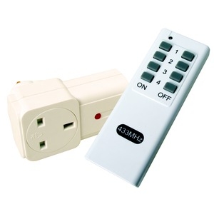
Maplin have recently had special offers on remote-controlled mains sockets - as cheap as £5 for a socket and controller pair. Since the control frequency is on the standard 433MHz band, and I had a pair of Arduino-friendly 433MHz transmitter/receiver modules lying around, I thought I'd have a play to see if the control protocol can easily be reverse-engineered for use with the Arduino. So, I dutifully hooked the receiver module up to 5V and an oscilloscope, and started pressing buttons on the controller. Things looked promising - a simple ASK pulse train, probably Manchester encoded. 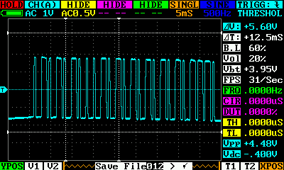 A single data packet. Not shown is the leading low pulse between each packet - approx 13ms. At first, I tried applying an open source Arduino Manchester encoding library, but soon realised that was going nowhere because it insisted on a long preamble of pulses to train its Phase Locked Loop (and to warm up the receiver's AGC circuitry), and there wasn't anything like that in this signal. The Manchester library uses AGC preamble because it is sending a single encoded data blob at a time. These RF sockets work more on the IR remote control principle, of repeatedly sending the same data while the button is pressed, so the first pulse train is effectively the AGC warm up, which is not necessary afterwards. Instead, the next thing I tried was to simply time the width of the leading high pulse, and assume that was half of the frame length of each Manchester-encoded bit. From that point, I could sample the pulse train at that interval, and retrieve each half-bit value, ready for decoding. I struggled for a while with that, until I realised that the long pulses were actually more like 3 times the width of the short pulses, rather than the 2 times that would be standard. So, I changed tack. I realised that I didn't actually need to decode the pulse train as if it was Manchester encoded. Instead, I could simplify things and simply count the length of time between state changes. I could treat long pulses as 1s, and short pulses as 0s. When concatenated, this would give a binary number unique to the incoming pulse train - assuming that the transmitter was sending an identical pulse train with each packet (which I was fairly sure of from monitoring with the oscilloscope). This new approach worked fine, and I was able to quickly map out the unique numbers for each button and channel on the remote control. (The remote has 4 selectable channels, and 8 buttons. The channels aren't real channels in the RF sense, but just different IDs sent in the pulse train). Here's the resulting Arduino sketch, which sends debug output to the serial console, and pulses a pin for a short period of time whenever it detects that the ON Button 1 on channel 1 is being pressed. This also compiles for ATTiny85 @ 8MHz, without the serial output. For some reason, it's less accurate at discriminating the buttons on ATTiny, and responds to all the ON buttons on channel 1. Sadly it's a lot harder to debug the ATTiny, so I'll probably leave it there for now. The receiver module needs to be connected up as per the datasheet. It looks like you need to be fairly strict about giving it an accurate 5V supply (easy from an Arduino, and I used a low power 7805 regulator with 6V (4xAA) battery pack for the ATTiny). Connect the analogue output (pin 3) to the microcontroller input pin (D9 on Arduino, PB3 on ATTiny). You'll see references to debug pins in the code. I used these, in conjunction with the oscilloscope, to make it much easier to see when the FSM state changed, and when the pulse train was being sampled. Without that, it would have been enormously harder to debug the code and circuit to get the whole thing working. This code could definitely be improved, especially for efficiency as it currently needs to run a tight loop for input sampling. Next step would probably be to convert it to use pin change interrupts instead - and to tidy up some of the cruft that resulted from its evolutionary development. A note on costs: Maplin are currently selling a bulk pack of 5 sockets and 1 controller for £20 (reduced from £30), but only until early April, which I think is a great price. So far I've only discussed how to use the controller - but I'll talk about how to address those 5 sockets from an Arduino in my next post. |
Donate!
If you have found my site or software useful, please consider donating a small amount of money using the button below.
|
|||||||||||||||||||||||||||||||||||||||||||||||||