CategoriesCalendar
ArchivesQuicksearchSyndicationStatisticsLast entry: 2012-09-11 21:41
38 entries written
446 comments have been made
3 visitor(s) this month
1 visitor(s) today
1 visitor(s) online
Powered by
|
Tuesday, January 31. 2012Automatic USB disconnectorI use a Linux box with a cheap (but extended-range) bluetooth dongle to monitor the invertor for my solar panels, and also my central heating monitor. This is fine, except that occasionally the bluetooth dongle seems to crash, and it needs to be physically unplugged to recover. Since there doesn't seem to be any comprehensive way to do this through software (you can reset the device, but it doesn't perform a power interruption so doesn't recover it sufficiently), I decided to make a little hardware dongle to do it for me. The design is extremely simple - just use an ATTiny to periodically (perhaps once a day) interrupt the 5V USB line. All other USB lines (data +/-, GND) pass straight through. Rather than power the attached device directly from an ATTiny I/O pin (which can only source ~40mA) I drive the attached device's power line through a PNP transistor (in this case rated at ~ 200mA, which is enough for my purposes, but 500mA would be needed for general purpose USB loads). Here's the schematic (drawn with Eagle, another experiment which turned out to be a lot easier to work with than Fritzing). Ignore the labelling as ATTiny13 - I actually used an ATTiny85. (There doesn't seem to be a directly usable part in the Eagle library, but the pinouts are the same). 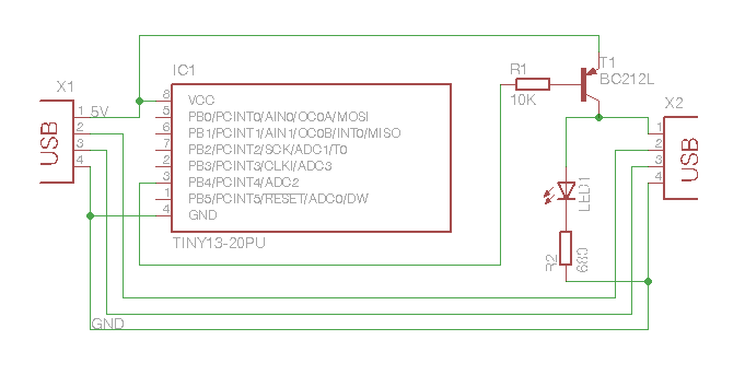 Schematic for USB power interrupter Note that since I only need one pin, I deliberately used one that's not involved in ISP programming, so that I can reprogram the ATTiny in-circuit if I ever feel the need. And here's the ridiculously trivial code:
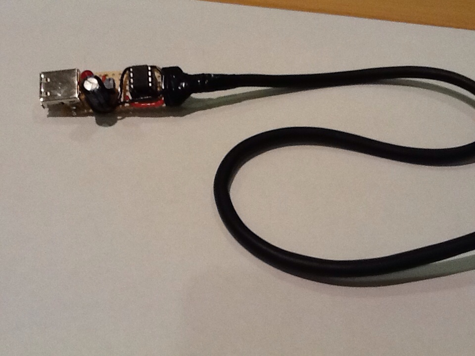
I didn't feel the need for any fancy power saving, since this will be drawing a trivial amount of current from an always-on USB port. I prototyped this on breadboard, and it did indeed successfully reset the bluetooth dongle. Next step is to transfer to a more permanent layout - probably just tripad board, for compactness, then fix up the delays, install it and forget about it! [UPDATE 2/2/12] Here's a picture of it moved onto tripad stripboard, with a permanent USB plug and socket. The sharp-eyed will notice an extra capacitor that's not in the schematic - because I forgot to draw it on there. It's an arbitrary low-value electrolytic capacitor - say 100uF - connected between the incoming USB 5V and USB 0V, to smooth current surges.
|
Donate!
If you have found my site or software useful, please consider donating a small amount of money using the button below.
|
|||||||||||||||||||||||||||||||||||||||||||||||||